
F16 Throttle Quadrant System (TQS)
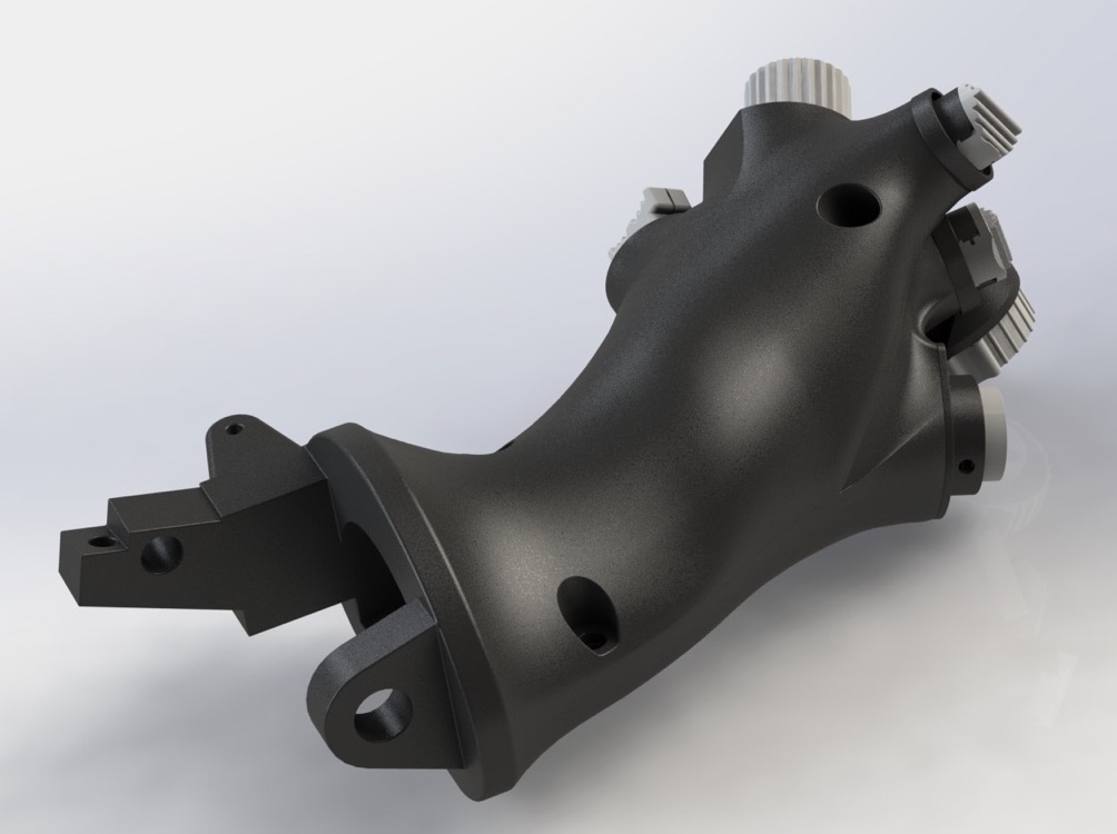
This is the F16 Throttle 3D model, also commonly known as Throttle Quadrant System (TQS). The model is based on a real F16 Model A TQS, measured meticulously by hand (no 3D scanner).
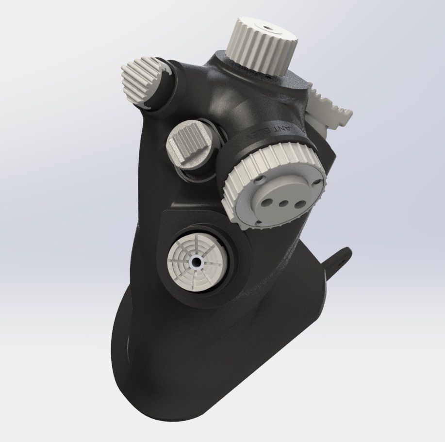
Switches only have their caps modeled for cosmetic look and accurate outside dimensions for fitting. The knobs of them are also modeled and added into the same directory. Please note that the cutoff level and pin are completely bullshit. I have no real cutoff lever and pin, I pull that out of my ass and the Internet. Absolutely bullock information on the cutoff level and pin. Do not trust any dimension from the cutoff-anything here. They are just “look-alikes.” However, since they don’t connect to anything outside of the throttle, and as long as it functions like the real one and feel comfortable, and looks right, I am fine with that. That is, this is the right place to BS.
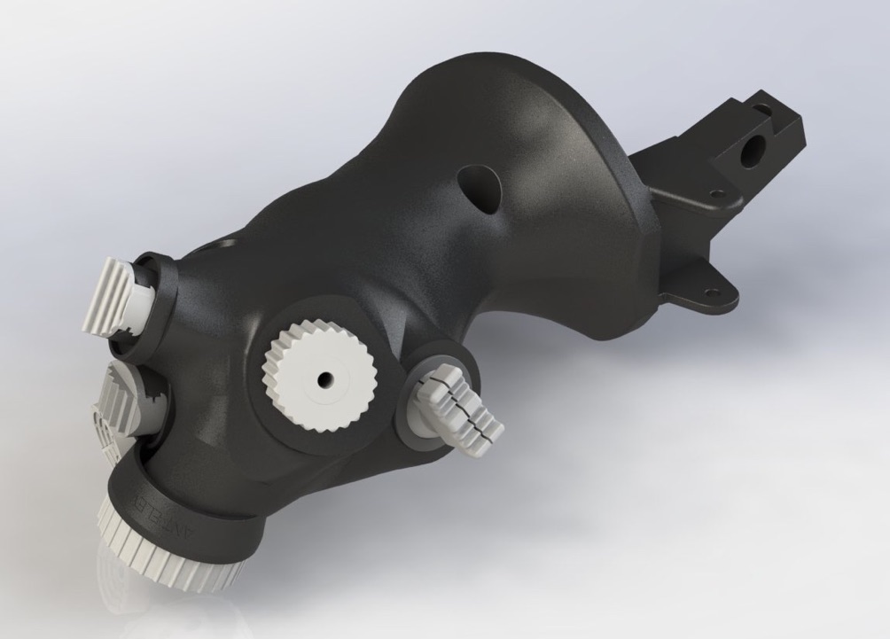
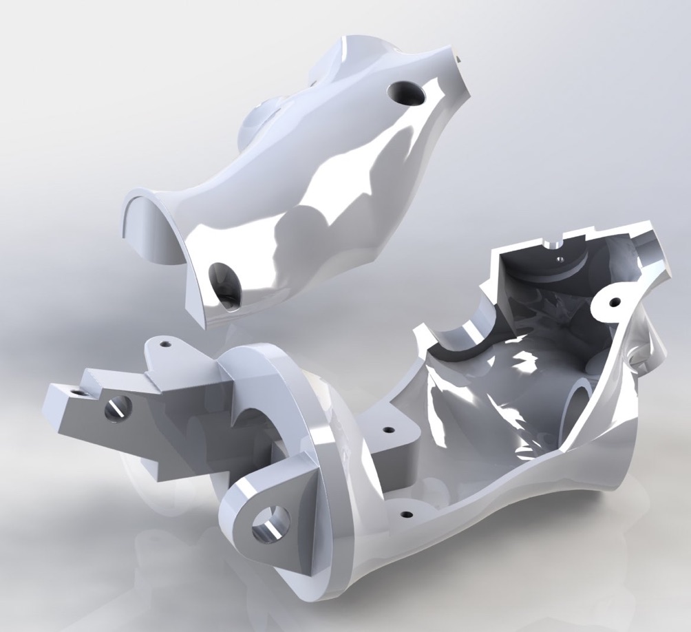
Internal shell is a bit of BS. The 3 “islands” for screws on both top and bottom shells are accurate, but the rest are a bit of a “about there” kind of modeling. It is basically a .11” individual shell patches that do not degenerate when “offset” by .11”, and then I manually patched the gaps and smoothed them out. If you are just going to 3D print it, you need no modifications. But if you use other manufacturing methods, like lost wax investment casting, you might want to modify it a bit and consider the drafting (I didn’t consider that).
The F16 Throttle Quadrant is arguably THE most comfortable HOTAS throttle quadrant EVER. Ok, I am biased, but that statement might not be too far from the truth. Yes, it is the most comfortable and form fitting throttle quadrant design I have seen, but it does have a little problem of hard to add additional functions. I mean, look at the A10 throttle quadrant. It’s a bit of a tapered block with a curved top, barely accommodating human hands. It’s not as form fitting and comfortable as the F16 one, but it has a lot of flat surfaces to add “stuff.” But if you look at the F16 one.... where the hell would you add one more HAT switch if you want to? Eh? Wherever you try to put it, it just look completely out of place!
And it’s one of the most difficult things I have modeled.
With this one, I am doing a little experiment by publishing only the Parasolid files.
Like I mentioned in the original Flight Sim 3D Model page, I set out to collect real parts and 3D model them. But I don’t want to be in the information control business. I knew there would be people who do not respect other people’s intellectual properties, so I removed almost all the incentives to “pirate” these files by publishing them under Creative Commons Attribution Non-Commercial International licenses. I mean, pretty much it’s free, as in freedom and as in beer both. I even went so far as if you want to use my models to make stuff and sell them, all you have to do is to donate the amount YOU feel appropriate to ViperPits for running their website, NOT MY website.
All I am pretty much asking for is, ok, you use my work, you acknowledge the work I put in. Man, I did the work, you say I did what I did instead of staying mum and pretending that you did all the work. That’s not cool! I already took out all the money factors, and I could not imagine there are still people who would “steal” that. Harsh words? Yes, they are, but in this case, I could hardly give in more! I mean, think about it. Say that you took my 3D models, and start making parts out of them and sell them. If you don’t acknowledge my contributions, I could be unknowingly paying YOU money for my works. That’s very uncool! Think about the absurdity of it all.
In addition, I am always very open about sharing knowledge. Solidworks files are that kind of Constructive Solid Geometry files with which to construct the final product, you pretty much “replay” every operations from the beginning. That is, Solidwork part files record every single operation from start to finish, and when you open them, the operations are “replayed” and re-computed in order to reconstruct the final model. And, there is a bar you can drag back to tell Solidworks to replay only up to certain point, allowing you to see the result of each step. Looking at other people’s Solidworks files could be very “educational” in learning how the other guys/gals constructed the solid(s). I always prefer to publish these files in raw Solidworks files so I might contribute a little to the snowball effect of collective knowledge of mankind.
Despite all those, there are still people in the central kingdom taking other people’s OpenSource design files, particularly Solidworks files, incorporating parts of them in their own Solidworks design, making parts out of them for sale, and not publishing their “derivative works, all without acknowledging original authors’ works. I mean, if they have done all that, including illegally making profit out of OpenSource’d IPs, but published their “derivative” works, I would a bit annoyed, but not pissed! I mean, after all, they still contributed to the collective human knowledge, albeit stealing other people’s credits. But no, they just had to take it all, but give nothing.
I don’t know why? I guess it’s just that in some countries, it’s in their culture and common practices that such kind of behavior is a social norm or something. I just couldn’t understand what kind of culture and common practices that would be so far apart from common decency. And I am from Taiwan, the pirate island of the ‘80s, done my bit of software piracy when I was a teenager. But, there is even honor among thieves, ok?
So, after considering many other options, balancing between the desire of wanting to share as much as possible, yet not allowing central kingdom to seal as much as they like, I decided to do a little experiment on this particularly one. The F16 throttle is particularly a good test case for this, in that it’s very difficult and complicated to construct, and the end result without the intermediate steps is still quite useful -- by publishing them only in Parasolid files. These Parasolid files, you can still import them into CAD systems, measure, modify, to get derivative works, or generate STL files for 3D printing. Yes, you can still steal my works, but at least you can’t steal my knowledge of how to construct it.
The original Solidworks SLDPRT and SLDASM files will still be available upon request, and of course, if you pass my personal scrutiny.
Enough of the rant. Why in the hell modeling this thing?
Look, there are plenty of Thrustmaster Cougar throttle out there, so old and plenty that you could probably pick one up for a song, particular after Warthog’s release. Yes, they are old, but they are pretty good facsimiles! These are close enough to the real thing unless you know exactly what you are looking for. As a casual observer, you wouldn’t be able to tell the difference from far! Moreover, there are several F16 throttle quadrant 3D models out there for free! Ah... but if you take a closer look at them, you would know they are WAY OFF the mark. One of them is constructed for an 1:5 model plane or something like that and it didn’t even pass a first glance test -- the distance between VHF/UHF and MAN RNG/Uncage stumps are way too far apart. The whole thing is way too stretched out, like a human face in horse proportion -- it looks just ... totally “wrong”, for the lack of better words.
Those are not reasons enough to undertake such a complex modeling work!
I have designed a Hall sensor Mini-Stick that I intend to patent the inner mechanism. The reason for designing this mini-stick is TM Warthog’s little cursor “nub”, in place of the Piezo-Electric force sensing Mason mini-stick, is completely unusable. Anybody who buys a Warthog stick would tell you that kind of IBM StinkPad like nub is just flat out garbage. For that Hall Mini-Stick, I need a test platform in addition to a modified Warthog. So, how about a completely new HOTAS? That’s a lot of work, but the intermediate step would be to duplicate an existing one, honing the manufacturing methods, before making my own design.
Then, I was inspired by the Markforged printers. It’s quite cool that you could print carbon/glass fiber re-enforced parts. But, it’s freaking expensive, and slow. It’s just not suitable for production parts except for some small volume and niche parts. The price range is just way outside the range of garages. I put that “dream” aside. But then one day it clicked... you know what? With traditional composite construction method, they put a foam core in the center and sandwich that core with carbon/fiber/Kevlar fiber and epoxy, outside and inside. The foam core sucks for tensile strength, but it is very good for compression. The tensile forces are taken up by the fibers, which are good for tensile forces but suck for compression. That’s how composites work in general. The foam cores are traditionally CNC milled, hot wired, knives carved, sanded, what have you. They are usually not molded. For foam, if it’s soft non-structural foam, it’s ok to mix the chemicals at home and have them expand, and fill the mold cavity. For instance, X-30 liquid foam is good for filling cavity of pontoons for floatation or of walls for sound proofing. But it’s not suitable as the core of a load bearing composite structure. But structural foams cannot be done at home. At least that’s what “they” all say and nobody would sell me the chemical and give me instructions on how to do that anyway. Hand carving... sucks... particularly you want organic shapes and precision. That leaves two method, 5 axis CNC milling and 3D printing. I don’t have a 5 axis CNC milling machine. Mine is only a 3 axis one.
What if I 3D print the core, say print at 95%, and then proceed with fiber composite construction? Could I get a part that as strong as Markforged printed? Sure, it would take longer for me to make the same part because after printing I still have to do the fiber lay up/vacuum works. But, at least my parts should be as good as theirs, for some cases.
I need a test platform for this construction method! It has to have complicated shape that is difficult to mold. Because if I can mold it easily, then why not just print the damned mold and either cast it in epoxy or do fiber lay up work anyway? What better than the F16 throttle Quadrant? Moreover, I already have a real one from block 15 at home that I can just measure it and model it. But you know what? There is a good reason why there is so few F16 throttle 3D models out there, and why I have the real throttle for years and never modeled it -- it’s tough!
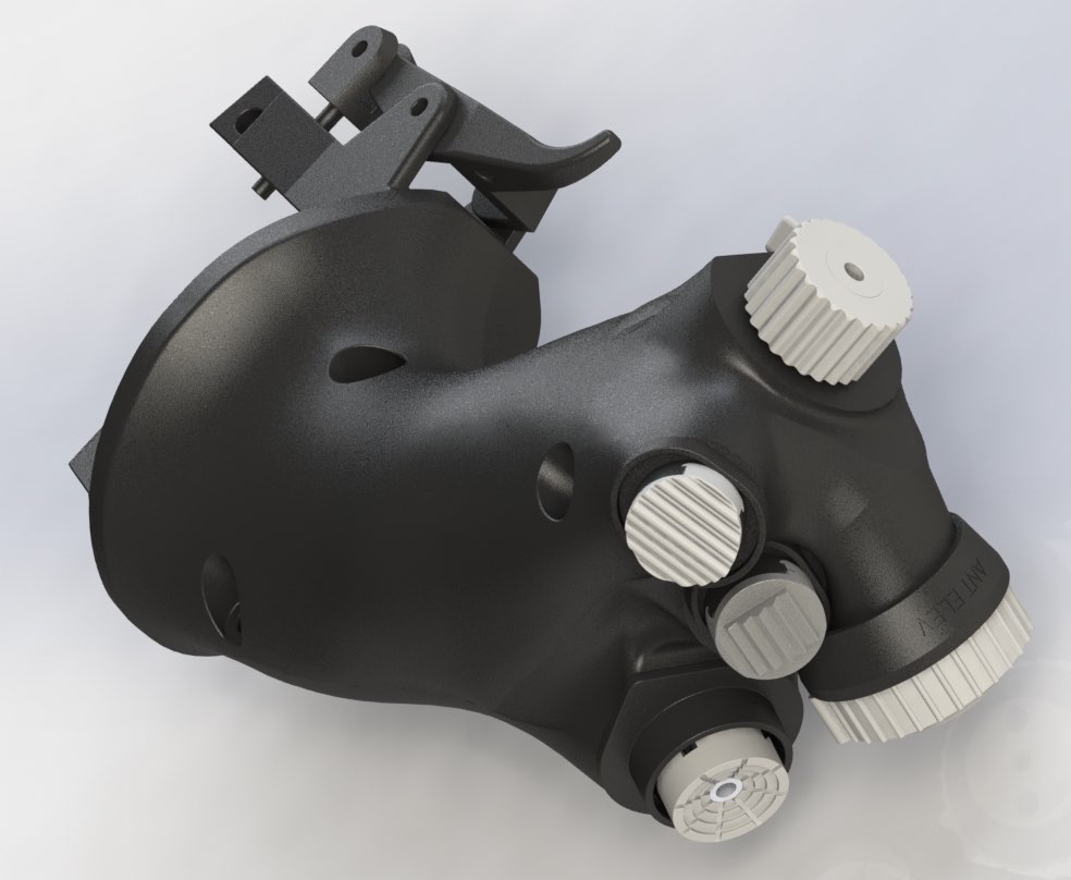
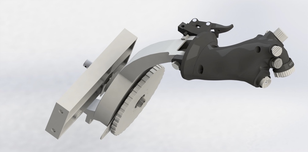
The last image below strictly does not belong here on this page. But, where else should it be? Whatever, I have the parts, I might as well aseemble and show off. ;-)
Data Source
National Stock No & ADD : 16P1873-883
Item Nomenclature : N/A
Model # :
Serial # : N/A
Manufacturer : Mason
Condition : Used
Inspection Date : N/A
Surplus Date : N/A
MFG Date : N/A
Original Price : N/A
Bought Price : N/A
Serviceable Label Not Available
The only marking on it is :
Created Date : July 28, 2017
Last Modification Date : Sept 4, 2017
Parasolid Files :
https://github.com/JonahTsai/F16/blob/master/Throttle/BottomBody.x_b
https://github.com/JonahTsai/F16/blob/master/Throttle/TopCover.x_b
Other Knob files also located at https://github.com/JonahTsai/F16/blob/master/Throttle/